IVS Technology
VGOS Concept
The VGOS architecture differs significantly from the S/X system and is mostly driven
by the needs for short source-switching intervals, improved delay measurement precision,
smaller drifts of the electronics, and improved automation and operational efficiency.
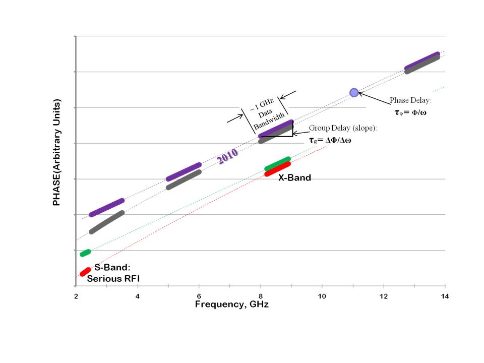
Of particular note is the change from a system with two fixed bands (S and X band) to a
system with four bands, each of which can be placed anywhere in the 2–14 GHz range.

The VGOS subsystems can be characterized as follows:
-
Antennas are relatively small (12 m or larger), fast slewing, and capable
of mostly unattended operations.
-
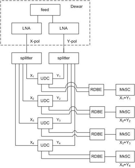
Feeds are cryogenically cooled with dual linear polarization and continuous
frequency coverage from 2 to 14 GHz.
-
Both linear polarizations are acquired, and all four polarization products
are processed at the correlator.
-
The front end receiver is comparatively simple and includes
-
broadband LNAs for the two polarizations,
-
noise and pulse calibration subsystems, which inject signals into the
receiver to calibrate the complex system gain down to the digitizer.
-
The broadband RF signals are transmitted directly from the receiver to the
control room on fiber optic cables. This minimizes the number of signal cables
between the receiver and control room and allows downstream analog processing,
such as frequency translation and filtering, to be done under better controlled
environmental conditions.
-
Four RF bands are processed, enabling the use of the broadband delay technique.
-
Each RF band is frequency-translated to the intermediate frequency (IF) range
(0–3 GHz) in a flexible up-down converter (UDC). The translation is done in
two mixing steps. The input is first shifted up in frequency with a programmable
synthesizer to put the desired portion of the RF band in a predetermined, fixed
frequency range. The signal then passes through a bandpass filter before being
translated down to IF, where it can be digitized.
-
The output of the UDC is sampled at 10 bits/sample and processed in the digital
back end (DBE). Input signals initially pass through 1-GHz-wide anti-alias filters
before sampling. Up to three Nyquist zones may be available. The sampled data
are then processed in a field programmable gate array (FPGA), the primary functions
of which are channelization, bit-truncation, and data quality analysis, including
power level measurement and calibration signal detection.
-
A hydrogen maser provides the frequency and timing reference signals for the pulse
calibration subsystem, the UDCs, and the DBEs.
-
Data are stored, at least temporarily, on disk recorders.
-
Recorded data are either shipped to the correlator on disk packs or, where possible,
transmitted over optical fiber.
-
Correlation is done in one or more software correlators.

|


